PQL Designs
+44 (0)1256 740680
PROVIDING CUSTOM DESIGN AND BUILD SOLUTIONS FOR THE THIN FILM COATING AND VACUUM INDUSTRY
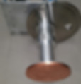
SUBSTRATE STAGES
SPECIALISTS IN THIN FILM SPUTTERING DEPOSITION SYSTEMS, COATING EQUIPMENT AND CUSTOM VACUUM COMPONENT DESIGN AND MANUFACTURING
Substrate Stages / Chucks /Holders For Sputtering Systems
Options:
Substrate Heating 800 Degrees C
Substrate Cooling -15 Degrees C
Substrate Rotation 5-60RPM
Substrate RF Bias 600watt
Z-shift
Load Lock Manipulator Compatible
Electrically or Pneumatically Operated Shutter
We have designed and built a variety of custom substrate stages for our “HiTUS” R&D customers, both in-house and external, covering a wide range of applications, substrate types and capability. These are provenly compatible with the high plasma density environment of the HiTUS sputtering systems, providing a robust basis for general vacuum use.
Our stages are designed primarily for ‘sputtering up’ use, but can in principle be mounted in any orientation.
Customisable to Suit User Needs
PQL Designs offer extensive customisation of R&D substrate holders to meet the often demanding requirements of forefront research, based on our proven designs for HiTUS sputtering systems. Options deriving from this are listed below, but we are always willing to discuss further developments that may be required.
Our substrate assembly's usually include rotation to assist with achieving coating thickness uniformity and an appropriately sized coating shutter.
Substrate stages are usually manually loaded via the vacuum chamber door; we have also built low cost designs for nitrogen glove box “load-lock” use (to improve system throughput) and have designs available for vacuum load-lock schemes.
Up to 150mm diameter / diagonal substrate area
Our standard substrate tables typically mount 100-150mm diameter / diagonal substrates, or multiple substrates covering the equivalent area.
For smaller substrates (20-30mm), we have an option to mount multiple substrates and use holder rotation (optionally process controlled) to index individual substrates to a coating aperture.
Mounting plates and physical masking options for single or multiple substrates
Stages can be designed for single and/or multiple substrate use, with interchangeable ‘clamp plate / substrate carrier’ sets to allow easy switching between the two. These plates can be integrated with physical masks to support prototype thin-film device fabrication builds.
Special designs for non-planar substrates
Inherent rotational capability and modular form allow flexible mounting options to be implemented to support 3D substrate coating, providing the basis for ‘best possible’ sputtering coating uniformity of complex shapes.
Pneumatic shutter with position indicator
Substrate carrier stage shutters are usually pneumatically actuated, either via operator panel switching or by the process control system. Separate shutter position indication is available for display or automation purposes to customer preferences.
Variable speed rotation
As standard the substrate chuck's rotation can be varied over the range 5 to 120 rpm, primarily to allow simple mounting and rotation of high mass substrates off centre (e.g. metal coupons). As with the shutter, rotation is disabled for safety reason during the load/unload process.
Stepper motor option for rotation
Where the rotation speed is required to be accurately controlled and consistent run to run, a stepper motor may be fitted for the substrate stage. This also allows the option for indexing individual (smaller than stage) substrates to coating apertures, allowing multiple deposition experiments within a single vacuum and coating cycle.
Vertical position (z-axis) adjustment
Simple engineering change allows substrate to flange distance to be manually altered run to run by the user for process optimisation. More complex design options allow this to be altered whilst the substrate stage is under vacuum, or even during the coating process, with potential significant benefits when coating ‘delicate’ substrate materials
Non-ferromagnetic construction
Provided as standard for full remote plasma source compatibility, this also allows the user to add a local “magnetic bias” or “secondary electron magnetic filter” element should this be desired.